- Home
- /
- News
- /
- Industry News
OTHER POWER ELECTRONIC DRIVERS

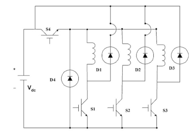
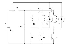
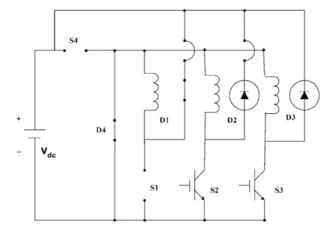
Figure 9.37 shows the SRM driver with Miller converter. In this configuration, there is one switch for each phase.
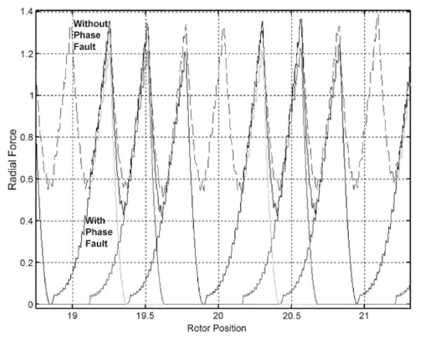
FIGURE 9.28 Radial force vs. rotor position with a fault in phase 2 from the dynamic modeling.
switches and diodes compared to the classic converter. Another advantages is that the Miller converter offers the lowest kVA inverter rating for a given drive power rating. However, the Miller converter has less flexibility. This is because the control angle range is limited since one switch is shared as the common switch. In addition, two phases of the machine cannot conduct simultaneously.
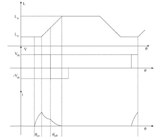
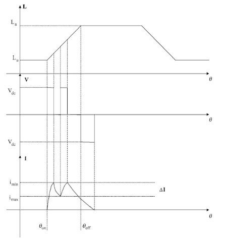
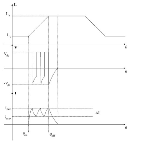
Figure 9.38 shows the phase inductance, voltage, and current for a Miller converter.
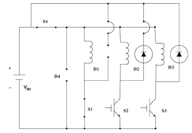
A Miller converter has three modes of operation in low speed. In mode 1, as shown in Figure 9.39, S1 and S4 are turned on and D1 and D4 are off. Input DC bus voltage is applied across the phase winding. Therefore, phase current increases. Input source current is
Phase current decreases until it reaches the minimum current set by the hysteresis control. Then S4 is turned on and the converter operates in mode 1. The converter switches between modes 1 and 2 until the turn-off time. At the turn-of instant, both S1 and S4 are turned off (mode 3 as shown in Figure 9.41). As a result, D1 and D4 conduct. Input DC bus voltage is applied across the phase winding with negative polarity. Therefore, phase current decreases until it reaches zero. During this mode, the input DC source is recharged.
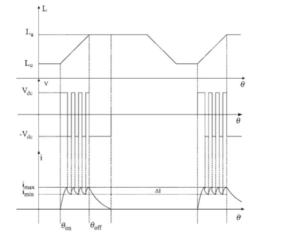
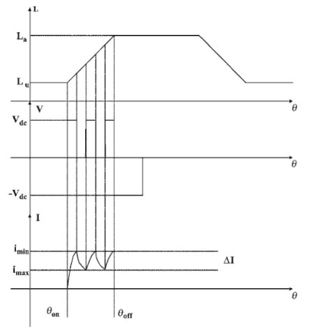
FIGURE 9.30 Phase inductance, voltage, and current for low-speed operation with hysteresis control.
9.6.2 R-Dump Converter
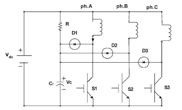
Figure 9.42 shows the SRM driver with an R-dump converter. In this configuration, there is only one switch for each phase without any common switch. Therefore, this is a low-cost SRM driver. However, the efficiency is low because of the dump resistor. Figure 9.43 shows the phase inductance, voltage, and current for an R-dump converter.
The R-dump converter has two modes of operation in low speed. In mode 1, as shown in Fig. 9.44, S1 is turned on. D1 is off since it is reverse biased because the capacitor voltage is applied across it with negative polarity. Input DC bus voltage is applied across the phase winding. Therefore, phase current increases. Input current is equal to the phase current. When the phase current
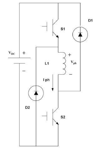
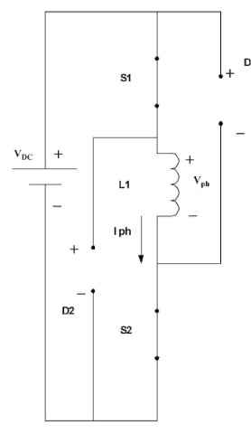
FIGURE 9.31 Equivalent circuit of one phase of a classic two-switch-per-phase SRM driver.
reaches the maximum hysteresis current, S1 is turned off (mode 2 as shown in Figure 9.45). D1 is forced to conduct. Since the capacitor voltage is greater than the DC bus voltage, a negative voltage is applied across the phase winding. Therefore, the phase current decreases. When the phase current reaches the minimum current set by the hysteresis control, mode 1 repeats. At turn-off time, the converter operates in mode 2 until the phase current reaches zero.
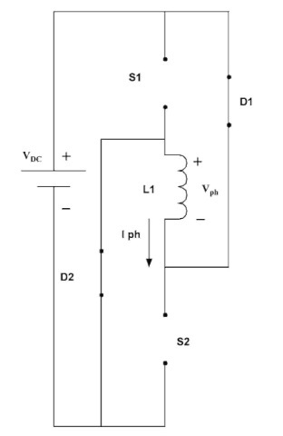
FIGURE 9.32 Equivalent circuit when the two switches are on.
Because of the resistive power loss in the dump resistor, in mode 2, efficiency of this driver is low.
9.6.3 C-Dump Converter
As shown in Fig. 9.46, in order to improve efficiency, instead of using a dump resistor like the R-dump converter, a C-dump converter uses an energy dump capacitor. This configuration is a
FIGURE 9.33 Equivalent circuit when the two switches are off.
single-switch-per-phase converter. Therefore, the packaging is compact. The DC source capacitor also has less ripple. In this topology, similar to the classic converter, both positive and negative DC bus voltage can be applied to the phase windings. This in turn provides control flexibility to improve the performance of the motor by reducing torque ripples and acoustic noise. However, the common switch has higher voltage and current ratings. Another disadvantage is that only motoring mode is possible. Figure 9.47 shows the phase inductance, voltage, and current for a C-dump converter.
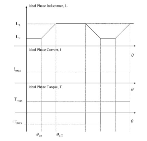
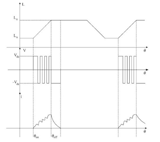
FIGURE 9.34 Phase inductance, voltage, and current for the unipolar switching.
The C-dump converter has seven operating modes. In mode 1, as shown in Figure 9.48, S1 is turned on; other switches and diodes are off. The input DC bus voltage is applied across the phase winding. Therefore, phase current increases. Input source current is equal to the phase winding current.
When the phase current reaches the maximum hysteresis current, S1 is turned off. As a result, D1 is forced to conduct (mode 2, Figure 9.49). In mode 2, D4 and S4 are also off. The voltage applied across the phase winding is – (Vc -VDC). Capacitor voltage is greater than the input DC bus voltage. The phase current decreases until it reaches the minimum hysteresis current. In mode 3, (Figure 9.50), all the switches and diodes are off. Phase voltage and current are zero.
FIGURE 9.35 Phase inductance, voltage, and current for PWM switching.
In order to maintain a constant voltage across the dump capacitor, S4, D4, and L4 form a DC/DC buck converter. It is a step-down chopper if the dump capacitor and DC bus are considered input and output, respectively. It is also a step-up chopper if the DC bus and dump capacitor are considered input and output, respectively.
The task of this DC/DC converter is to maintain the dump capacitor voltage. Figure 9.51 shows mode 4 when S4 is turned on while S1 is conducting. Figure 9.52 shows mode 5 when S4 is on while D1 is conducting. Both modes 4 and 5 can be used to charge the dump capacitor. However, common practice is to use only mode 4 for this purpose; therefore, mode 5 is not used as mode 4
FIGURE 9.36 Phase inductance, voltage, and current for high-speed operation.
is enough to charge the dump capacitor. Simplicity is the advantage of mode 4 compared to mode 5.
In mode 6, D1 and D4 are on and S1 and S4 are off. In mode 7, S1 and D4 are on and D1 and S4 are off. In the most popular approach for the C-dump converter, only modes 1, 4, 6, and 2 are used consecutively.
9.6.4 Freewheeling C-Dump Converter
Figure 9.53 shows the SRM driver with freewheeling C-dump converter. Figure 9.54 depicts the phase inductance, voltage, and
FIGURE 9.37 SRM driver with Miller converter (n + 1 topology).
current for this drive. This is also from the family of single-switch-per-phase converters. AC-dump converter cannot provide a zero voltage across the phase winding. Therefore, C-dump drivers always use bipolar switching schemes. However, a freewheeling C-dump converter can provide a zero voltage across the phase winding. As a result, a unipolar switching scheme as shown in Fig. 9.54 can be used. Reduced acoustic noise and torque ripples are the main advantages.
9.6.5 Split-DC Converter
Figure 9.55 shows the SRM driver with split-DC converter. Figure 9.6 depicts the phase inductance, voltage, and current for split-DC converter. In this configuration, a split-DC supply converter is used. The main disadvantage of this topology is derating the supply DC voltage.
This is because only half the DC bus voltage is utilized as the applied voltage across the phase windings.
It should be noted that there are several other converter topologies for SRM drives. They include the buck-boost converter,
FIGURE 9.38 Phase inductance, voltage, and current for Miller converter.
FIGURE 9.39 Equivalent circuit when S1 and S4 are on.
FIGURE 9.40 Equivalent circuit when S1 and D4 are on.
FIGURE 9.41 Equivalent circuit when D1 and D4 are on.
FIGURE 9.42 SRM driver with R-dump converter.
FIGURE 9.43 Phase inductance, voltage, and current for R-dump converter.
variable DC link voltage converters, the Sood converter, soft switched converters, and resonant converters.
Newer articles
- Tips for Keeping gearheads cool (05/05/2017)
- The Benefits of Gearboxes — and When to Pick Integrated Gearmotors (05/05/2017)
- How to Calculate the RPM of a Motor and Speed Reducer (09/07/2017)
- What is a Gearmotor? What are its Uses? Why Dolin gear reducer motor? (12/08/2017)
- Advantages And Disadvantages Of Single Phase Motors (04/05/2017)
- DC motors advantages and disadvantages over AC motors? (01/08/2017)
- The different types of gears (09/11/2017)
- Advantages and disadvantages of different types of gears (01/09/2018)
- Advantages & Disadvantages of Electric Motors (04/05/2017)
- What are Brushless DC Motors (31/05/2019)
Older articles
- Gearbox Motors vs Integrated Gearmotors (16/04/2008)
- AC or DC? brushed DC or brushless DC Gear Motor? (24/04/2008)
- Dolin seeks help in identifying poor “reliability” in electric motors (02/02/2007)
- WHAT TO CONSIDER WHEN SELECTING A GEAR REDUCER OR GEAR MOTOR (22/11/2012)
- Applying Gear Ratios to DC Motor Systems (08/11/2013)
- What Does Gear Reduction (Gearbox) actually mean for DC gearbox motors? (22/11/2012)
- 4 Common Worm Gear Applications (11/11/2010)
- What is a Reduction Gear? (09/10/2009)
- Light-Load hair foil its high quality (02/09/2009)
- Have a gear motor special designed (04/09/2011)


Join